Circuit board components are essential for modern electronics, enabling devices to function by controlling, storing, or directing electrical energy. Identifying these components is crucial for troubleshooting, repairs, and design.
1.1 Importance of Component Identification
Identifying circuit board components is vital for troubleshooting, repairs, and designing electronic circuits. It enables understanding of device functionality, ensures safety, and facilitates proper maintenance and upgrades. Accurate identification prevents errors, enhances reliability, and streamlines the diagnostic process, making it a fundamental skill for electronics engineers and hobbyists alike.
1;2 Brief Overview of Circuit Boards
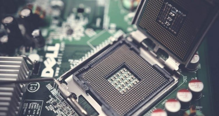
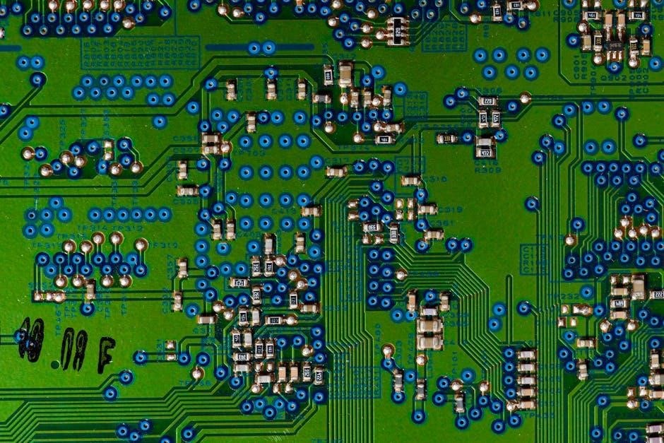
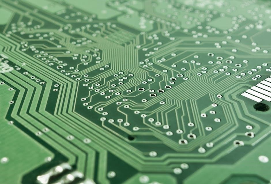
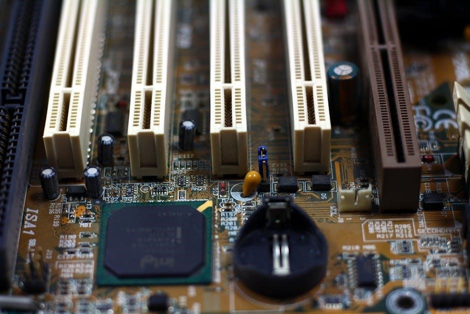
A circuit board is a flat, insulating material with conductive pathways etched onto its surface, connecting various electronic components. It serves as the backbone of modern electronics, enabling devices to function by integrating resistors, capacitors, diodes, and other elements. The board’s design and component arrangement determine the device’s functionality, making it indispensable in all electronic systems.
Classification of Circuit Board Components
Circuit board components are categorized into passive, active, and specialized types, varying in function and complexity to serve distinct roles in electronic circuits.
2.1 Passive Components
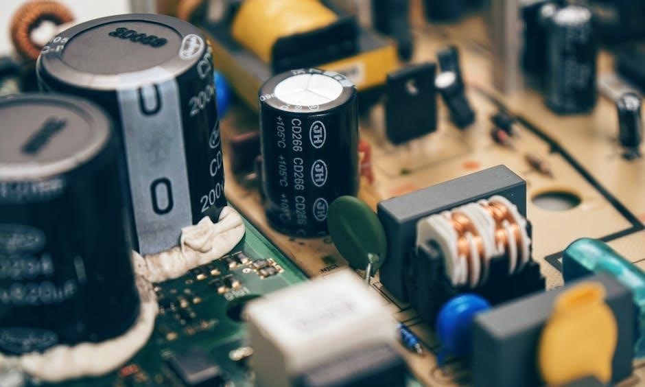
Passive components, such as resistors, capacitors, and inductors, do not require an external power source to function. They store, filter, or regulate electrical energy, playing a fundamental role in circuit operations. These components are essential for controlling current flow, filtering signals, and ensuring stable voltage levels in various electronic applications and designs.
2.2 Active Components
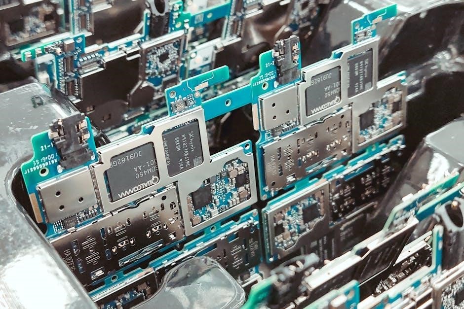
Active components, including diodes, transistors, and integrated circuits (ICs), require an external power source to operate. They amplify, switch, or modify electrical signals, enabling complex functionalities in circuits. Diodes allow unidirectional current flow, while transistors act as switches or amplifiers. ICs house multiple components within a single package, enhancing functionality and reducing circuit size.
2.3 Specialized Components
Specialized components include connectors, switches, LEDs, LCDs, and buzzers, serving unique functions. Connectors link boards or devices, while switches control circuit connections. LEDs emit light, LCDs display info, and buzzers produce sound. These components enhance user interaction and functionality, making them indispensable in modern electronic designs for communication, feedback, and control systems.
Visual Identification Techniques
Visual identification involves recognizing components by their physical appearance, shape, size, and markings. This method helps in quickly identifying resistors, capacitors, diodes, and ICs for troubleshooting and circuit understanding.
3.1 Identifying by Physical Appearance
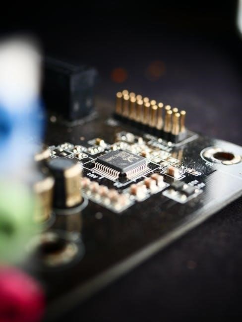
Physical appearance is a key factor in identifying circuit board components. Resistors are cylindrical or rectangular with color bands, while capacitors vary in shape, from cylindrical to ceramic. Diodes often feature a silver or white ring, and transistors are typically black or gray with three pins. ICs are square or rectangular with printed information.
3.2 Recognizing Component Shapes and Sizes
Component shapes and sizes vary, aiding identification; Resistors are cylindrical with color bands or small rectangles. Capacitors may be cylindrical, disc-shaped, or rectangular. Diodes often have a distinct band. Transistors typically have three legs, while ICs are square or rectangular with multiple pins, varying in size and pin count. Recognizing these forms helps in quickly identifying components on a circuit board.
3.3 Common Component Markings and Labels
Components on circuit boards are marked with labels indicating their type, value, and function. Resistors use color bands or numeric codes, while capacitors display capacitance and voltage ratings. Diodes are marked with part numbers, and transistors feature model numbers. Integrated circuits have manufacturer logos and model numbers. These labels are essential for quick identification and troubleshooting, ensuring proper circuit functionality and repair. Component numbers like R1 or C2 also indicate their role in the circuit.

Reading Component Markings and Codes
Component markings reveal critical data like resistance, capacitance, and part numbers. Resistors use color bands, while capacitors display capacitance and voltage. Diodes and transistors feature part numbers for easy identification, ensuring proper functionality and repair.
4.1 Decoding Resistor Color Bands
Resistors use color bands to indicate resistance values and tolerances. The first two bands represent significant digits, the third denotes the multiplier, and the fourth shows tolerance. For example, a resistor with bands red (2), violet (7), red (x100), and silver (10%) has a resistance of 2700Ω with a 10% tolerance. This coding system simplifies identification and ensures accurate circuit design and troubleshooting.
4.2 Understanding Capacitor Markings
Capacitors are marked with numerical values in microfarads (µF) or picofarads (pF), often accompanied by voltage ratings and tolerance codes. For example, “10µF 25V” indicates a 10 microfarad capacitor rated for 25 volts. Some capacitors use abbreviations like “n” (nano) or “p” (pico) for smaller values. Tolerance codes like “J” (±5%) are also common. Always verify markings for proper circuit operation and safety.
4.3 Interpreting Diode and Transistor Codes
Diodes and transistors are identified using part numbers like 1N4148 or 2N2222. These codes, often found on the component or datasheet, specify electrical characteristics. Diodes may have polarity markings (e.g., a silver band for the cathode), while transistors are identified by their pin configurations and packages. Cross-referencing these codes with datasheets ensures accurate identification and application in circuits.
4.4 Deciphering Integrated Circuit Numbers
Integrated circuits (ICs) are identified by unique part numbers printed on their packages. These numbers, such as “LM324” or “NE555,” correspond to specific functions and specifications. Datasheets provide detailed information about pin configurations, voltage ratings, and operational parameters. Decoding these numbers helps in understanding the IC’s role and ensures proper application in circuit designs and troubleshooting scenarios.
Tools and Resources for Component Identification
Essential tools include multimeters for measuring resistance and capacitance, reference datasheets for specifications, and online databases for component libraries, aiding accurate identification and troubleshooting.
5.1 Using Multimeters for Component Testing
Multimeters are indispensable for testing circuit board components; They measure resistance, voltage, and capacitance, helping verify component values. Use the ohmmeter function for resistors and diodes, and capacitance mode for capacitors. Ensure proper connections to avoid damage. This hands-on approach complements visual identification, providing precise data for accurate component verification and troubleshooting.
5.2 Reference Datasheets and Manuals
Reference datasheets and manuals provide detailed specifications, pinouts, and functional descriptions of components. They are essential for accurate identification and troubleshooting. Datasheets list technical parameters, while manuals offer installation and usage guidelines. Consulting these resources ensures compatibility and proper functionality, aiding in precise component identification and circuit board assembly.
5.3 Online Databases and Component Libraries
Online databases and component libraries are invaluable resources for identifying circuit board components. Platforms like Digi-Key, Mouser, and component libraries in PCB design software provide detailed part information, datasheets, and cross-references. These tools enable quick identification by searching parameters or part numbers, enhancing accuracy and efficiency in component recognition and procurement for both hobbyists and professionals.
Polarity and Pin Configuration
Understanding component polarity and pin configurations is crucial for proper circuit functionality. Diodes and capacitors often have marked polarities, while transistors and ICs require correct pin alignment to function correctly.
6.1 Identifying Component Polarity
Component polarity is critical for proper circuit operation. Diodes and capacitors often feature visual markers, such as a silver band or plus sign, indicating their positive terminal. Transistors and ICs require referencing datasheets for correct pin orientation. Ensuring proper polarity prevents damage and ensures functionality, making it a key aspect of circuit board assembly and repair.
6.2 Understanding Pin Arrangements
Pin arrangements vary among components, with transistors and ICs having specific configurations. Datasheets provide detailed diagrams, often using numbering and orientation markers. Correctly matching pins ensures proper connections and functionality, preventing errors in circuit operation. Understanding these layouts is vital for accurate assembly and troubleshooting, enhancing overall circuit performance and reliability. Always refer to specifications for precise alignment.
6.3 Common Soldering Techniques
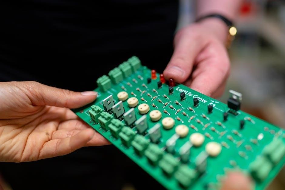
Soldering is critical for securing components to circuit boards. Techniques include through-hole soldering for leaded components and surface-mount soldering for SMDs. Tools like soldering irons, hot air guns, and reflow ovens are commonly used. Flux pens improve solder flow, while desoldering tools like pumps or braid remove excess solder. Proper soldering ensures reliable connections and component longevity.
Advanced Identification Techniques
Advanced methods like thermal imaging, automated recognition systems, and X-ray inspection enhance component identification. These techniques detect faults, analyze internal structures, and improve accuracy in complex circuit boards.
7.1 Using Thermal Imaging for Fault Detection
Thermal imaging detects temperature anomalies in circuit boards, identifying faulty components like resistors or capacitors. Infrared cameras reveal hotspots, aiding in troubleshooting without dismantling the board, ensuring efficient diagnostics and preventing damage.
7.2 Implementing Automated Recognition Systems
Automated recognition systems utilize AI and image recognition to quickly identify components, enhancing efficiency in mass production. These systems analyze PCBs using cameras and algorithms, reducing human error. Future tools may integrate AI for real-time component identification, such as smart multimeters that measure resistance and display ratings, streamlining electronics manufacturing and quality control processes effectively.
7.3 Utilizing X-Ray and Microscopic Inspection
X-ray inspection allows for non-destructive analysis of internal components and solder joints, revealing hidden defects. Microscopic inspection provides high-resolution images of surface-mounted components, identifying issues like cracks or corrosion. These advanced techniques ensure precise identification and quality control, maintaining high standards in circuit board manufacturing and repair processes effectively.
Safety Precautions and Best Practices
Always wear protective gear and ensure proper grounding to prevent static discharge. Store components in a dry, organized environment, and use appropriate tools to avoid physical or electrical damage.
8.1 Handling Components Safely
Always handle components by the edges to prevent damage from static discharge or physical stress. Use anti-static wrist straps and mats to ground yourself. Avoid touching sensitive pins or components with bare hands, as oils and moisture can compromise functionality. Store components in protective packaging to prevent physical damage and contamination.
8.2 Preventing Static Discharge Damage
Static discharge can severely damage sensitive electronic components. Use an anti-static wrist strap or mat to ground yourself. Ensure the workspace is conductive to prevent static buildup. Avoid walking on carpets or wearing synthetic fabrics that generate static. Regularly touch grounded metal objects to discharge static electricity before handling components.
8.3 Proper Storage and Organization
Store circuit board components in anti-static bags or containers to protect from moisture and dust. Label each container with the component type and value for easy identification. Keep components in a cool, dry environment away from direct sunlight. Use organizers or bins to separate and categorize components, ensuring they remain secure and prevent damage during storage.
Future Trends in Component Identification
Future trends include automated testing, advanced imaging, and AI-driven analysis for efficient identification. Eco-friendly manufacturing and miniaturization will also shape component design and recognition processes.
9.1 Integration of AI and Machine Learning
AI and machine learning are revolutionizing component identification by enabling automated recognition systems. These technologies use cameras and algorithms to analyze components, improving efficiency in mass production and quality control. Smart tools can now identify types and parameters, enhancing precision and reducing human error in complex electronics manufacturing processes.
9.2 Augmented Reality (AR) in Electronics
Augmented reality is transforming electronics by overlaying digital information onto physical circuit boards. AR glasses can display component details, pin configurations, and real-time data, aiding technicians in identification, troubleshooting, and design. This technology enhances efficiency, reduces errors, and streamlines complex tasks, making it a powerful tool for modern electronics engineering and maintenance.
9.3 Miniaturization and Its Challenges
Miniaturization of circuit board components presents significant challenges, including difficult identification, complex manufacturing, and reduced reliability. Smaller components, like SMDs, require advanced tools for inspection and testing. Higher density PCBs increase the risk of overheating and signal interference. This trend demands innovative solutions to maintain quality and performance in compact electronic designs, complicating maintenance and repair processes.
Mastering circuit board component identification is crucial for electronics work. It combines visual inspection, understanding markings, and using tools, fostering innovation and continuous learning in the field.
10.1 Recap of Key Identification Strategies
Effective circuit board component identification involves understanding classification, visual inspection, and decoding markings. Use tools like multimeters, reference datasheets, and online databases. Recognizing polarity, pin configurations, and leveraging advanced techniques like thermal imaging or AI-driven systems enhances accuracy. Continuous learning and adaptation to new technologies ensure mastery in identifying and working with circuit board components efficiently.
10.2 Encouragement for Continuous Learning
Continuous learning is vital in electronics due to rapid advancements. Staying updated with new technologies like AI and AR in component identification ensures adaptability. Engaging with online resources, courses, and communities fosters growth. Embrace lifelong learning to enhance skills, solve complex problems, and keep pace with evolving industry demands and innovations.